
Toppobrillo’s TWF was designed in 2010 and is now discontinued. But you can still build one. SynthCube sells the PC board with several different panel options. I chose the black Barcode panel for looks, though it’s made from PC board material. The panel set includes a pot and jack PCB designed by Barcode that plugs right into the main PCB, avoiding the panel wiring needed on the original TWF.
Sourcing parts
SynthCube provides only their own Bill Of Materials (BOM) as documentation. I suggest looking at synthCube BOMs for the other panel versions. The one I downloaded was missing the 10 47pf capacitors. Also look at the old SDIY site for TWF documents.
The headers I used for hooking the boards together:
Mouser 649-77311-118-03LF, male three and four-pin (-04LF) versions
Mouser 649-76308-103LF, female three and four-pin (-104LF) versions
Half-inch standoffs listed in the BOM were too long at 12.5mm for the headers I bought. I ordered 11mm standoffs with m2.5 threads, Mouser 710-970110151.
The build
There aren’t any step-by-step instructions for building this module. But it shouldn’t present much difficulty for a builder with some experience. I did the headers last, assembling the two-board sandwich with the standoffs before soldering them.

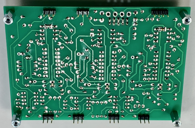
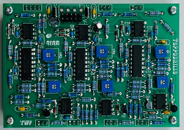
The board is well made and easy to solder. But the identifiers are under the parts. There’s no pictorial guide for placement, so I took the above photo for reference. Not listed in the BOM are five spots on the bottom for SMD bypass capacitors. I added them.

There’s a small error in the PC board. One of the 0.1 bypass cap leads is left unconnected to ground. I left the lead long enough to bend over and reach the pad for one of the trim pots (right side in photo). No one would notice any difference if it wasn’t connected anyway.


A little demo video
Notes on use
Create complex timbres from audio sources. The possibilities are really limitless. You can control each series of harmonics via the BIAS panel controls. So the overall sweep through the folds when using the VC ALL/ MANUAL controls is very flexible and since each stage of the folding process is VC’able, you can use different modulation sources simultaneously for wild animation/ phasing/ beating with a single tone source.
The normalized DC bias at input 1B can be used to control the symmetry of the folding process, via the control knob, when the input is not in use.
CV Processor for LFOs, envelope generators, sequencers or any control source. Create multiple interesting rhythmic modulation sources from an otherwise dull one. Useful in creating more complex, continuously variable shapes for modulation or timing.
Accurately multiply/ square up an input signal. Shape your triangles and sawtooths into very pure sinewaves. Mangle your sinewaves or anything else into very unpure asymmetrical fuzz. Generate a cosine function relative to your VCO’s triangle/sine output (useful for quad panning, stereo modulation). You can do a couple of these things at the same time with different sources.
All of the inputs and pots on the left side are for fold control voltage. The CV inputs respond only to positive voltages, 0 to +8 volts. That’s why I used a cycling envelope generator for the LFO. Each CV input sums with the fold pot value. The sensitivity of the three separate fold CV inputs is lower than the VC1 and VC2 CV inputs.

Two signal inputs 1A and 1B mix into wave folder 1. 1B has an attenuator that is normalled to a DC voltage, so that when nothing is patched to 1B the pot can impart an offset to the input signal.
The module can be looked at as having one signal input and up to four CV inputs. Or as having four signal inputs, three outputs, and up to three CV inputs. You could call it patch programmable. Note that the ALL CV mixer is completely detached if all three individual CV inputs are patched. It’s worth studying the block diagram! Another thing to note is that the three outputs can be externally mixed.


Hi, built a twf after much hassle, was told 0.1 if for the smd but .01 seems better which pots did you use (50k ,or 100k) and does 15 v give better range?
Hi Ellen,
I used 50K pots. The SMD caps are for power bypass. Everyone seems to use 0.1uf (100nf), which I keep in stock. As for the 15V power supply, I don’t know what the difference would be.