
I’m going to compare the features and behaviors of two relatively new complex random modules, the Ultra-Random Redux from Steady State Fate, and BAGÀI from Frap Tools. There is some feature overlap, but each of these sports some clever ideas. I’ll look at each in turn and then do some comparison.
Ultra-Random Redux
The Ultra-Random Redux is a new and revised version of the original Ultra-Random Analog from SSF. The biggest difference from the old URA (which I had, and sold) is the removal of the internal clock.

I’ve decorated the URR with Bananuts to help with identifying the jack functions. Silver indicates the trigger inputs, Gold the bi-polar signal inputs, Blue the uni-polar CV inputs, Red the pulse output, and Black the bi-polar outputs.

I’ve drawn a block diagram of the URR, above, since the manual doesn’t have one. Internally connection of the A trigger input cascades to the B trigger, and B to the Flux trigger. The Toggle S&H follows the B trigger. Patching the Random Pulse to the A trigger is a way to kick it all off. Note: the trigger inputs expect a sharply rising pulse
There are two identical Sample & Holds, each with its own noise source and rectifier switch. The signal coming into the S&H can be full or half-wave rectified, or left as-is. The Toggle out switches between the two S&H output.
Next is the Random Flux, which requires a trigger to be patched. A flux delta knob and CV input control the rate of change. There’s also a Flux Probability input that is bi-polar and can influence the flux offset from zero volts. The Flux output wanders in the +/-5V range. How far it wanders can depend on the rate of incoming triggers. The shape looks much like a wandering envelope generator.

The Random Pulse section has an internal free-running clock with a manual divisor knob to select from division by 1 to 128. The G-Sync switch selects between this internal clock or the clock patched into A or B trigger. The Density knob and CV input also modify the rate of pulse generation. I saw no impact of the division knob when triggering from A or B. The R-Pulse output amplitude is from zero to +11V when free running, but follows the positive height of an external trigger input.
Finally there is the VC Linear Slew. It’s input is taken from R-Pulse if nothing is patched.

Frap Tools BAGÀI

BAGÀI is my first Frap Tools module. The beautiful aluminum panel has colored etchings that actually are helpful, once you understand all the functions. Again, I’ve decorated with Bananuts. This is especially helpful in the top row where the silver Burst Clock Input stands out from all the outputs. Notice the CV attenuators sprinkled around.

Note that the GATE block in the diagram is an internal on/off switch, letting a signal pass or not.
Clearly BAGÀI is quite a bit more complex than Ultra-Random Redux. Thankfully there is a block diagram in the manual and I have redrawn it with more clarity (to my eyes, anyway). We’ll go top down on the diagram, starting with Fluctuating Random Voltage (FRV). An internal clock, S&H, and integrator comprise the FRV. FRV clock rate and probability distribution each have knobs and CV inputs. Rate CV input has an attenuator. Probability distribution is similar to Flux Probability on URR.
FRV is also called the “Global Rate of Change“, since it impacts both random outputs and the burst output, more of which later.
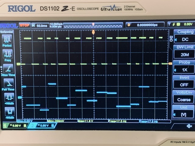
The internal noise source is high amplitude, +/-10V. Since it’s the source for the FRV and also the default source for the Sample & Hold, those outputs have this range as well. Notice the 10V/division on the scope, below. FRV meanders with quite a good shape variety.

The Noise output is always available, being passed through a manually adjustable filter.
BAGÀI has two internal CV controlled clocks, low and high speed, both under the same knob and CV input with attenuator. Everywhere these clocks go internally can be overridden by external clocks. The single Sample & Hold of BAGÀI can be clocked by either the slow or the fast clock, or an external clock.
Clock outputs
The internal slow clock is normally connected though a pulse generator, where it can be overridden by the Clock Input, which will only affect the three main clock outputs. It does not impact the S&H or the Burst (there are separate clock inputs for those). The pulse generator creates precise 2ms pulses and this is the pulse width of all the three outputs, main, plus, and minus. Before reaching the main clock output, this pulse must pass a gate that can disable these clock outs. The gate is controlled by the yellow button OR’ed with the Clock Hold Gate. Pressing the button or sending a high gate will pause the clock outputs. The plus clock out gets additional 2ms pulses that vary according to the FRV. The minus clock out gets fewer 2ms pulses than the main clock, also varying with the FRV. So the pulse width remains the same, but the occurrence changes.

Burst
The Burst output is made from two sources, either of which can be disabled. The first burst source is a pulse train varied by the FRV and can be gated off by a low gate at the Burst Gate input (normally hooked to a positive voltage internally to enable it). The second source is the internal slow clock, but which can be overridden by an external Burst Clock, or a dummy cable to disable it.
Sample & Hold
Input to the S&H is normally the internal noise, but can be overridden by an external input (gold jack on my panel). The S&H trigger is normally the internal clock, slow or fast, and this also has a jack to override. Using the fast clock with an audio input facilitates down-sampling. The S&H output is passed to a Quantizer and Bit Depth reducer, which has a knob and CV with attenuator for the bit depth. This is available on a separate output.

A Quick Feature Comparison
Ultra-Random Redux has the benefit of two sample and holds, each with a different noise source, and with optional rectification. It also has the Toggle S&H output and the separate Linear Slew. Random Pulse is really random gates and can make digital noise, as well. Lacks CV attenuators.
BAGÀI has a separate noise output and two different ways of doing random pulses relative to the main clock. The internal clock can run the S&H at two rates, and even run the S&H fast while running the main clock and the burst at the slow rate. Pulse out width is fixed. Quantized bit reduction is another added feature. All the internal normal connections make it simple to get going, while still having many override possibilities.
Each module take a different approach to making a wandering random voltage. It’s nice to have both.

Though I didn’t report this in the post above, I had measured the Quantized S&H output 1-bit (max bit reduction) as 600mv to -10V. The manual calls this a gate, but I thought it’s weird to have a negative gate, since virtually all gate inputs have some positive voltage threshold. I emailed Frap Tools about it and they wanted to get my unit into their lab. They paid the shipping and I sent it. Today I got the following reply.
“Your Bagài was perfectly fine and the values you measured are compatible with every other unit.
The 10 V p/p are indeed the extreme values of the noise and fluctuating circuits: even though we the RMS value is a bit smaller, it is still higher than +/- 5 V, so we’ll update the manual.
The gate between 600mv and -10V is also a normal behavior: it’s the result of having only bit 1 active. In our 8-bit circuit, the knob removes one bit at a time until it reaches the rightmost position, where only bit 1 is active. Being it a binary circuit, its output can only be a gate signal, or a square wave. Its theoretical values should be -10 and 0 V, covering half of the available spectrum of +/- 10 V. (600 mV is an offset pretty hard to remove in a device that’s not meant to be a lab tool). The second bit covers half of the remaining half, and so on until, with a network of 8 bits, it is possible to achieve 256 values more or less centered around 0 V.”