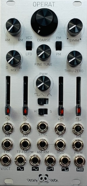
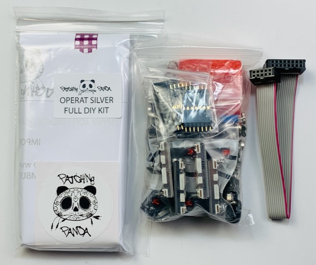
I bought a Patching Panda Operat oscillator full kit from Modular Addict. It is based on the SSI2130 integrated circuit, the same as used in the LA 67 T-ZED oscillator I recently built. In contrast to the T-ZED, Operat has many more features and is a more complicated build. This post will cover the DIY build only.

Operat is a marvel of jam packing a lot of stuff into a 12 hp Eurorack module. It is a three-PCB design. The PCB with all the panel parts also contains a lot of circuitry. But the assembly instructions consist of just two pages of photos and not a lot of text for guidance. Steps 1-5 are simple enough. Just soldering a few parts onto the two PCBs.

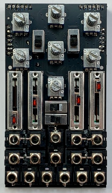
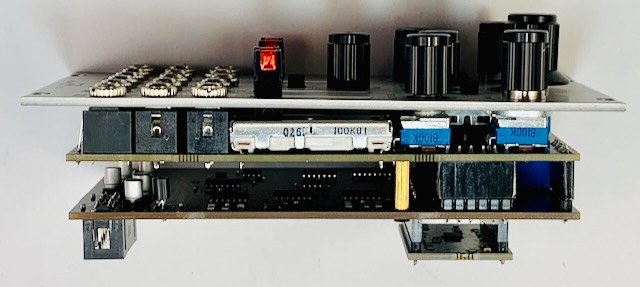
Pictured above, the two boards are shown after step 5. The four connectors linking the boards have been soldered. The faces showing will be sandwiched together, ending up on the inside. Now comes the somewhat difficult phase of mounting all the panel parts. Patching Panda calls this “quite a complex build.” That normally doesn’t faze me at all. However I did run into a few things that did make it harder. The first thing is that you are soldering very close to pre-soldered SMD parts and also close to the connector headers you just finished. Care is needed to avoid these with the soldering iron. I also found that my Kester 245 Sb63Pb37 No-Clean 0.8mm solder did not flow as nicely as usual on these boards.
Assembling the panel parts
The instructions starting with Step 6 become somewhat confusing. Step 6 indicates installation of the seven rotary pots, all the same value. After snapping them into the board, they seated well. I soldered them. The next step I took was to place and solder the slide pots. All of the pots seat snugly without wiggle room, and so are safe to solder.
After all the pots soldered in, I placed the jacks and tried the panel fitment. Here’s where things don’t line up. The jacks stand quite a bit above the height of the pot bushing bases. Enough washers are supplied that two can be used on each pot to raise the support for the panel. But the panel still angles downward from the jacks to the pots. I found some thicker washers to use, but put them only on the top three pots.

Also in the above photo I’ve circled in red the two small holes where the screws have to go for the standoffs between the boards. More on this later.

Because of the angled panel, the thicker washers could not fit behind the other pots. Only the top three pots had enough thread to catch the nut. Since the pots are solidly soldered into the board, I decided to forget about putting nuts on them. After securing the three pot nuts and putting jack washers on the four corner jacks, I finished soldering the jacks.
Pesky switches
Now all that was left was the six slide switches. I removed the panel again. It’s a little tricky getting the switches to go under the panel because they wobble around. But after they were in and the panel secured by the three pot nuts and all of the jack washers came time to solder the switches. Problem there was how to hold them from wiggling around during soldering, since the holes are much larger than the switch pins.

I used some carpenter’s tape to hold the outer pins of a switch while I put a bit of solder on the middle pin. The pins need to be centered in the holes as well as possible in order to position the switch right under the rectangular hole in the panel. After tack soldering the middle pins, I checked and made adjustments as needed before soldering the remaining pins and retouching the middle pins.

Final assembly
With all the soldering done, all that’s left is final assembly. First step: finish installing the panel — whoops! After putting all the nuts on the jacks and pots, I sadly discovered that the standoff screw holes had become inaccessible. So I had to remove the panel once again to attach the rear PCB.

You can see how the panel slopes downward toward the pots. I did my best to reduce this, but there isn’t enough thread on the pot bushings to lift the panel higher with washers.
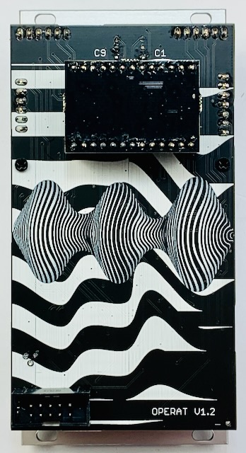
Also notice that the back PCB where the power header lives is cantilevered out from the gold standoffs, leaving poor support when connecting the power cable. Be careful not to bend the board when attaching the power cable!
The final step is to insert the mini-PCB into the headers on back.